Sealless Pumps for a Safer and Greener World

As electric vehicle ownership expands, home charging is becoming essential rather than optional. The International Energy Agency’s Global EV Outlook 2025 reports that electric car sales exceeded 17 million in 2024. Electric vehicles represented more than one in five new cars sold worldwide. This growth increases demand for dependable residential charging equipment.
An Ac Wallbox Charger is a fixed charging unit installed beside a parking space. It connects the vehicle with the building’s AC electrical supply. When the charging cable is connected, the wallbox and vehicle exchange control signals. The system checks connection status, grounding, and available current before delivering power. The wallbox normally does not convert AC into battery DC. Instead, the vehicle’s onboard charger performs that conversion. Typical residential models provide between 3.6 and 22 kilowatts. Actual charging speed depends on wiring, vehicle capacity, and installation limits. A higher power rating does not always mean faster charging.
The U.S. Department of Energy’s Alternative Fuels Data Center describes Level 2 charging as commonly using 208–240-volt AC power. It generally charges much faster than a standard household outlet. In practical use, a 7.4-kilowatt wallbox may add meaningful range overnight, while a 22-kilowatt model can be limited by the vehicle itself. That distinction is easy to miss. IEC 61851-1 also defines important conductive charging control requirements. Safe installation still requires suitable protection, correct cable sizing, and qualified electrical work. The picture is not perfect. Weather, load management, and household demand can change results, so charger specifications should be read alongside real driving habits.
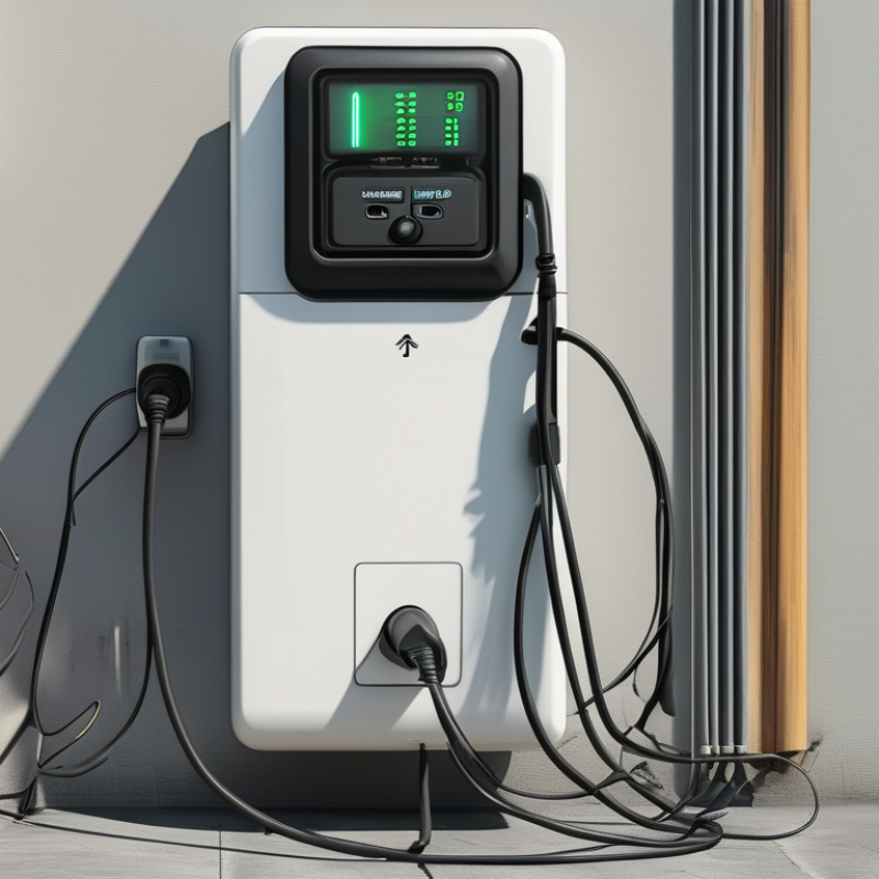
An AC wallbox charger connects an electric vehicle to a building’s 208–240 V AC supply. Unlike a DC fast charger, it does not usually convert electricity inside the wallbox. The vehicle’s onboard charger performs that conversion, changing AC power into DC power for the battery.
Charging output commonly ranges from 3.7 to 22 kW. A 3.7 kW unit may use a modest current and suit overnight charging. A 7.4 kW wallbox often works with 240 V single-phase power and can add useful range during several hours. Higher outputs require stronger wiring, suitable circuit protection, and careful load calculations. A 22 kW rating may depend on three-phase power, so it is not automatically available from every 208–240 V installation.
The real charging speed depends on three limits: the wallbox, the vehicle’s onboard charger, and the electrical supply. The lowest limit controls the result. A car accepting only 11 kW will not charge at 22 kW, even when the wallbox supports it. A qualified electrician should verify conductor size, breaker capacity, grounding, and continuous-load requirements before installation. Small details matter.
In practice, smart load management can reduce output when a building uses ovens, heat pumps, or other heavy equipment. This prevents unnecessary upgrades, although it may extend charging time. The advertised power figure is useful, but it needs context.
An AC wallbox charger connects an electric vehicle to the building’s alternating-current supply. The power path looks simple, but each stage has a different job. The IEA reported more than 14 million electric cars were sold worldwide in 2023. That growth makes reliable home charging increasingly important.
Grid AC enters the wallbox through protected wiring. The EVSE then checks grounding, cable connection, and charging readiness. It does not usually convert the electricity. Instead, it communicates with the vehicle and controls the permitted current. A pilot signal can tell the car whether 16, 32, or another ampere level is available. Safety comes first. IEC 61851 defines this control approach for conductive charging.
The vehicle’s onboard charger performs the major conversion. It changes AC into controlled DC for the battery pack. A common 7.4 kW system uses about 32 amps at 230 volts. Actual charging may be slower. Battery temperature, state of charge, and household load all matter. The U.S. Department of Energy’s Alternative Fuels Data Center identifies Level 2 charging as commonly using 208–240-volt AC supplies. That range explains why installation details cannot be copied blindly between regions.
There is a small but important imperfection. Wallbox power is not battery power. Conversion losses occur inside the onboard charger, and cable resistance adds more. A display showing 7.4 kW may deliver slightly less to the cells. Measuring energy at the meter gives a more honest result.
| Power-Path Stage | What It Does | Electrical Form | Typical Ratings or Values | Control and Protection | What Happens to the Energy |
|---|---|---|---|---|---|
| 1. Utility Grid | Supplies alternating current to the building or charging site. | AC mains electricity | Single-phase: approximately 120 V or 230 V Three-phase: approximately 400 V line-to-line in many regions | Protected by the building service panel, circuit breaker, grounding system, and residual-current protection. | Electrical energy is delivered to the dedicated charging circuit before entering the wallbox. |
| 2. Dedicated Branch Circuit | Transfers grid power from the distribution panel to the wallbox. | AC | Common continuous charging currents include 16 A, 24 A, or 32 A. The circuit is normally sized above the intended continuous load. | Uses correctly rated conductors, overcurrent protection, grounding, and installation hardware. | Limits the available current according to the building wiring and protective-device rating. |
| 3. AC Wallbox Enclosure | Provides a fixed, user-accessible charging point and houses the switching and communication hardware. | AC input and controlled AC output | Common output levels: approximately 3.6 kW, 7.4 kW, 11 kW, or 22 kW. | May include contactors, temperature monitoring, overcurrent detection, ground-fault or residual-current monitoring, and emergency shutoff functions. | The wallbox generally does not convert grid AC into battery DC; it manages and safely passes AC to the vehicle. |
| 4. EVSE Control Pilot | Communicates the charging status and the maximum current that the vehicle may draw. | Low-voltage signaling over the charging cable | Uses a control-pilot signal defined by common conductive AC charging standards. The signal can advertise an allowable current, such as 16 A or 32 A. | Prevents power delivery before a valid vehicle connection is detected and coordinates charging states. | The vehicle uses the advertised limit to configure its onboard charger and avoid exceeding the permitted current. |
| 5. Proximity and Connection Detection | Confirms that the connector is inserted and helps manage cable or latch status. | Low-voltage signaling and connector circuitry | Connector-specific; ratings vary by regional charging interface and cable assembly. | Can prevent charging while the connector is not fully seated or while the plug is being removed. | Improves user safety and reduces the risk of arcing or accidental disconnection under load. |
| 6. Wallbox Contactor | Connects or disconnects the AC conductors under electronic control. | Switched AC | Rated for the maximum continuous voltage and current of the charging circuit. | Normally closes only after the vehicle and EVSE complete the required safety checks. | Allows the wallbox to stop power flow during a fault, charging completion, overheating, or user-initiated interruption. |
| 7. Charging Cable and Connector | Transports AC power and signaling between the wallbox and the vehicle. | AC power plus control signals | Common current classes include 16 A and 32 A. Cable assemblies may be tethered or removable. | Connector temperature, mechanical locking, insulation condition, and conductor size must be suitable for the current. | Conductive losses occur in the cable and connector and increase with current and resistance. |
| 8. Vehicle Inlet | Receives AC power and communicates with the EVSE. | AC input to the vehicle | Maximum voltage, phase count, and current depend on the vehicle's charging system. | Mechanical locking and vehicle-side monitoring help prevent unsafe connection or removal. | Passes the permitted AC power to the onboard charger rather than directly to the battery pack. |
| 9. Onboard Charger (OBC) | Converts incoming AC into regulated DC suitable for the high-voltage traction battery. | AC input, isolated or controlled DC output | Common vehicle charging capacities range from approximately 3.3 kW to 22 kW. Many vehicles support one-phase charging; some support three-phase charging. | Controls voltage and current, manages isolation, monitors temperature, and follows battery-management commands. | Most of the conversion loss occurs here, so the battery receives slightly less power than the wallbox delivers. |
| 10. Battery Management System | Determines how much current the battery can safely accept. | Low-voltage control data and battery DC parameters | Charging limits vary with battery state of charge, temperature, cell voltage, and battery condition. | Can reduce or stop charging when the battery is cold, hot, full, or outside safe operating limits. | Protects the cells and controls the charging profile, typically reducing power near a high state of charge. |
| 11. Traction Battery | Stores the electrical energy for vehicle propulsion. | High-voltage DC | Passenger EV battery packs commonly operate in the several-hundred-volt range; exact voltage varies by vehicle design. | Cell balancing, voltage monitoring, thermal management, contactor control, and insulation monitoring are used. | Stores energy chemically and later supplies DC power to the vehicle inverter and motor system. |
| 12. Charging Power Calculation | Estimates the AC power available from the electrical supply. | Electrical calculation | Single-phase: P ≈ V × I Three-phase: P ≈ √3 × VLL × I × power factor | Actual power is limited by the lowest rating among the grid circuit, wallbox, cable, vehicle inlet, and onboard charger. | Example: 230 V × 32 A is approximately 7.4 kW before conversion and distribution losses. |
| 13. Charging Efficiency | Describes how much grid energy becomes stored battery energy. | Energy conversion and distribution | Overall efficiency varies with load, temperature, standby consumption, cable losses, and vehicle design. | Smart power management can reduce overheating and prevent the site from exceeding its available capacity. | Some energy becomes heat in the wallbox, cable, onboard charger, battery, and auxiliary systems. |
| 14. Charging Completion | Ends or pauses the charging session when the vehicle reaches its requested limit or charging conditions change. | Controlled AC shutdown | Charging may stop at a selected state of charge, scheduled time, or vehicle-defined limit. | The vehicle requests a stop, and the EVSE opens its contactor after the current is safely reduced. | Power flow ends, while the vehicle may continue monitoring the battery or remain connected for a later session. |
An AC wallbox charger is a dedicated electrical unit that safely connects an electric vehicle to the grid. It usually does not convert alternating current into battery-ready direct current. The vehicle’s onboard charger performs that task. The wallbox manages access, current limits, protection, and communication.
Charging control depends heavily on SAE J1772 and IEC 61851. SAE J1772 defines a control-pilot connection widely used for vehicle-to-charger communication. IEC 61851 describes the operating logic between the electric vehicle supply equipment and the vehicle.
A small pilot signal can indicate whether the cable is connected, charging is permitted, or a fault has appeared.
The pilot signal also communicates available current. The vehicle measures this signal before requesting power.
For example, a residential wallbox may advertise a lower current when several household loads are active. A control circuit then opens or closes the power contactor.
The vehicle’s onboard charger adjusts its demand accordingly. Proximity detection can help prevent cable removal while current flows.
In practical installations, the signal is only one part of safety.
A damaged connector may interrupt charging before any visible warning appears. That detail is easy to miss.
Standards also allow regional differences, so technicians should verify the applicable edition and local electrical requirements.
Pilot communication is reliable, but it is not magic. Poor grounding or incorrect configuration can still produce failed sessions.
An AC wallbox charger supplies alternating current to an electric vehicle through a dedicated circuit. The vehicle’s onboard charger converts that current into DC for the battery. This conversion creates the main charging limit. A powerful wallbox cannot force the car to accept more energy than its onboard charger allows. That distinction matters.
Charging speed depends heavily on voltage and amperage. At 240 volts, a 32-amp connection delivers about 7.7 kW. A 48-amp connection provides roughly 11.5 kW. The 19.2 kW ceiling usually requires 80 amps at 240 volts, plus a vehicle designed to accept it. Higher output also demands correctly sized wiring, protection, and professional installation. More amperage is not always better. Household service capacity can become the practical limit.
Battery capacity changes the time required, even when charging power stays constant. A larger battery stores more energy, so reaching full charge takes longer. State of charge also affects the result. Charging often slows significantly beyond 80 percent. Near full. Battery temperature can reduce power as well, especially during cold weather. In real garage use, displayed charging speed may fluctuate by several kilowatts. That is normal, but it should not be ignored. A common mistake is comparing a wallbox rating with actual battery input. The vehicle, circuit, temperature, and SOC all share responsibility.
An AC wallbox charger supplies alternating current to an electric vehicle, while the vehicle’s onboard charger converts it into battery power. The wallbox controls the connection and communicates basic charging limits. It does not usually perform the main AC-to-DC conversion. During installation, a qualified electrician checks cable size, breaker capacity, and the building’s available load. A tidy installation is not automatically a safe one.
Reliable grounding gives fault current a controlled path and helps protective devices disconnect power quickly. The circuit also needs suitable RCD or GFCI protection, depending on local electrical requirements. These devices monitor leakage and can interrupt charging when insulation fails or moisture enters the system. Test buttons should be checked during commissioning, not ignored after installation. I still recheck terminal tightness. Small errors can remain invisible.
Tips: Keep the charger away from standing water and damaged cables. Confirm the grounding path with proper test equipment. Set load management when several high-power appliances share the panel. It can reduce charging speed, but prevents nuisance trips and overheating. Leave clear space around the enclosure for inspection. Record test results, breaker settings, and the installation date. A qualified installer should review unusual wiring, older panels, or uncertain grounding before charging begins. 一级a做爰片
The protective earth conductor provides a low-resistance path for fault current so the protective device can disconnect the circuit.
Residual-current or ground-fault protection helps reduce shock risk. The required device type and trip rating depend on local electrical codes and the EVSE design.
Smart load management can reduce charging current when the building approaches its available electrical capacity, helping prevent circuit overload.
Nominal AC output is calculated as voltage × current using a 230 V single-phase supply. Actual charging power may be lower because of voltage variation, installation limits, vehicle settings, and charging losses. A qualified electrician should verify conductor sizing, overcurrent protection, grounding, and local RCD/GFCI requirements.


